


Roof-Mounted Front Light
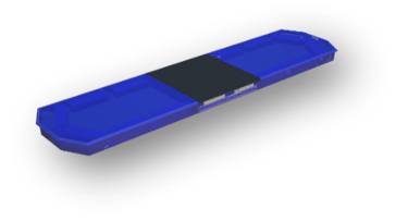
It is mounted on the front upper part of your ambulance. It is opened using the control panel switch located in the driver's cabin.
Rear Roof-Mounted Light
It is mounted on the rear upper part of your ambulance. It is operated using the control panel switch located in the driver's cabin. The LED spotlights facing the rear automatically turn on when the rear door is opened.
Exterior Side Lighting Lamps
There are blue lights on the right and left sides of the ambulance. They are controlled by the siren device and have an attention-grabbing feature. They are generally used in conjunction with the light-bar system. Amber-colored lights activate when the doors are opened.




Air Conditioning
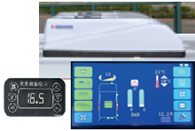
The air conditioning system, consisting of the evaporator unit located in the upper part of the driver's cabin and the condenser unit located in the upper ceiling part, regulates the climate in the patient cabin section. The system's power is provided by a compressor connected to the lower right part of the engine compartment. The control panel and electrical wiring operate independently of the vehicle's wiring system. The air conditioning system is bidirectional and can be controlled either from the patient cabin or the driver's cabin as desired.


Sound and Warning System
It is mounted on the front grille area of your ambulance. Its functions include hand, horn, and radio connections. It can provide a sound output power of 100W.
Heater
It is located at the bottom of the medical equipment cabinet in the patient cabin. Connected to your ambulance's original fuel tank, heating is achieved through fuel feed. The heater, controlled by its original switch and directly connected to the battery, is thermostatically controlled. It automatically disables when the temperature rises and activates when it drops. It can be operated as long as there is fuel in your ambulance's tank and for as long as desired, without needing the ambulance to be running
Digital Electrical Panel and Outlets
When the master module key is on, direct power is supplied to the 12V sockets. Power is supplied to the 220V sockets only when the master switch and the inverter device are on. These sockets are configured for the use of medical devices inside the ambulance.
Master Module Key
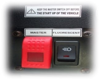
The master module key is the switch that transmits power from the ambulance's battery to the rear cabin via a relay. If the key is off, no power is supplied to the patient cabin, and consequently, none of the functions, including lighting, operate. This key is located on the left side of the steering wheel in the driver's compartment and is red in color.
Oxygen Pipeline
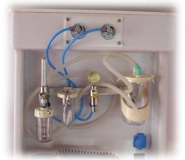
Two pressure reducing valve assemblies are provided to be mounted on the main and reserve oxygen cylinders. Each pressure reducing valve assembly is equipped with two pressure gauges. One gauge indicates the high pressure (inlet pressure) and is divided into 10 bar (100 kPa) intervals, with a scale ranging up to 315 bar (31,500 kPa). The other gauge (low pressure) shows the oxygen pressure delivered to the system. These gauges are of a type that can be easily read by the assisting personnel sitting in the companion seat or adjacent seat, depending on the installation of this assembly. The pressure supplied to the system by the pressure reducing valve is reduced to 4.5 bar (450 kPa). A safety valve (safety valve) is located at the rear of this pressure reducing valve assembly.
Epoxy Floor Coating
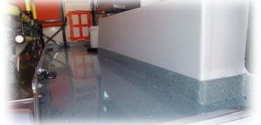
The floor of the ambulance patient compartment is covered with a single piece of epoxy material that does not contain asbestos, is washable, and is antibacterial. The floor covering extends up the side walls by 10cm to provide waterproofing. A 16mm thick MDF (Medium Density Fiberboard) panel is placed as a single piece on the floor, ensuring its flatness.






Inverter
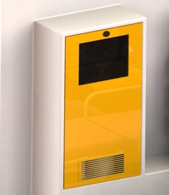
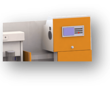
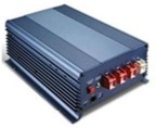
The device that converts the 12V DC power from your ambulance's battery into 220V AC power and supplies this energy to the 220V blue sockets is called an inverter. It can be turned on or off from the digital control panel using the inverter on/off button when the master module key is on.
Rectifier
In situations where your ambulance's battery is weakened and the ambulance will not be running for an extended period, an external device converts 220V AC power to 12V DC to keep your ambulance's battery fully charged. To operate, 220V power is supplied to the 220V input socket located on the left side of your ambulance. The master switch is turned on, and the rectifier is activated by pressing the rectifier on/off button on the digital control panel.
Oxygen Cabinet Compartment
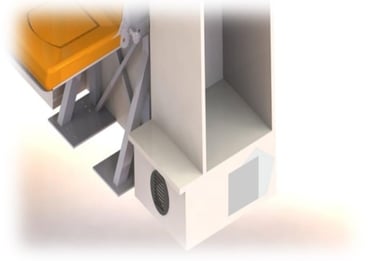
The oxygen cabinet compartment in the ambulance is designed to allow oxygen cylinders to enter and exit easily without leaving any gaps when viewed from the rear, ensuring a snug fit. It has a locked door at the front. Inside the cabinet, there are two (2) oxygen cylinders
Vacuum Stretcher Compartment
The vacuum stretcher compartment is placed in the space behind the doctor's seat in the separator compartment of the ambulance.
The Separator Front Cabinet and Doctor's Seat
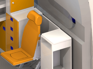
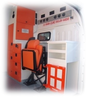
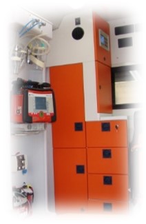
The ambulance cabinet system consists of three separate sections. The first section comprises four compartments with lockable covers to prevent drawers from opening during vibrations. The second section is designated for medical bags, which are either mounted or secured with belts to prevent them from being affected by vibrations. In the middle of these two sections, there is a second doctor's seat. Behind the seat, there is a space for placing the vacuum stretcher.
Doctor's Seat
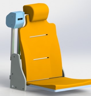
The doctor's seat is designed to allow direct intervention to the patient on the platform between the oxygen cabinet and the medical equipment cabinet in the ambulance. The seat can also be rotated towards the direction of movement of the ambulance. Its key features include occupying minimal space and being foldable. The exterior of the seat is covered with vinlex and has a maximum load-bearing capacity of 200 kg. The doctor's seat consists of three parts: the headrest, the backrest, and the seating area.
Medical Equipment Cabinet
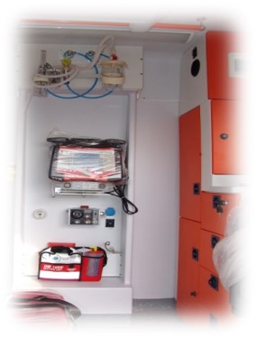
The Medical Equipment Cabinet is located on the left side wall of the ambulance, next to the doctor's seat, positioned closest to the patient's head. This placement ensures that the devices are easily accessible for the doctor to intervene. At the top of the cabinet, there is a defibrillator. In the middle section, there is a ventilator device, and at the bottom, there is a portable vacuum aspirator. Inside the cabinet, there are also electrical outlets for 12V and 220V power supply required for the operation of the defibrillator and ventilator, as well as oxygen sockets.
Medical Supply Cabinets
The medical supply cabinets are mounted on the left side wall adjacent to the separator compartment of the ambulance. The cabinet consists of two drawers and five compartments. It is designed to store adjustable collars, inflatable splints, body bags, burn kits, and other similar items.
Ceiling IV Drip Hangers
The ambulance's ceiling lighting system is positioned at the exact center of the ceiling, providing the most suitable location for the patient.
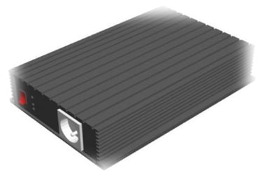










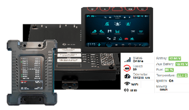
The CONTROL hardware we can offer upon request includes advanced intelligent Electronic Control Units (ECUs) designed for emergency vehicles. These systems provide centralized control of all automotive electronics. Its prominent features are:
• User-Friendly Reporting Software: Simplifies maintenance and troubleshooting with built-in diagnostics.
• Multiplexers: Reduce wiring complexity and bulk, making installations simpler and more reliable.
• Compact and Durable Design: Fits seamlessly into various environments and vehicle types, ensuring durability under different conditions.
• Flexible Configurations with Various Models: Offers diverse input/output configurations to meet different needs, ensuring compatibility with a wide range of vehicle systems.
• Remote Diagnostics and Real-Time Data Streaming: Enables continuous monitoring and proactive maintenance with real-time data transmission.
Each model in the CONTROL hardware series is designed to meet the specific requirements of complex vehicle systems, enhancing operational efficiency and vehicle management.

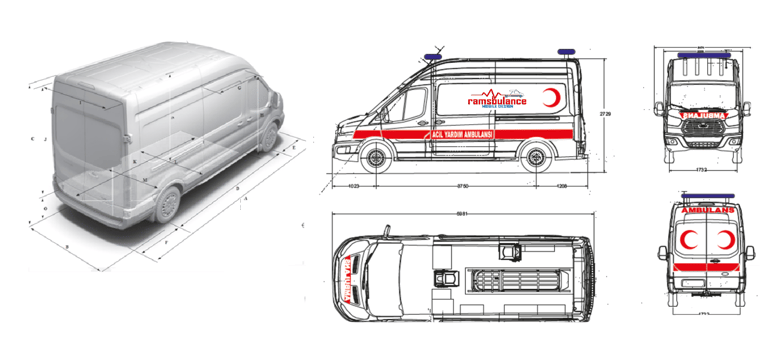
AMBULANCE TECHNICAL INFORMATION
© 2014. All rights reserved.
